[previous] [next] [contents]
![]() Information
required to test the non-BS clusters
Information
required to test the non-BS clusters
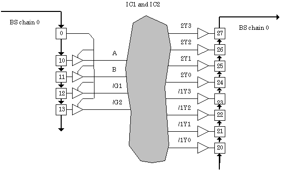
The first cluster comprises IC1 and IC2 (74LS139 and
74LS04) and is surrounded by BS cells of chain 0 only, as shown in figure
1.

Figure 1: The 74LS139 and 74LS04 non-BS cluster.
The information required for generating the test program segment concerning this cluster, besides the test vectors generated externally, comprises the elements presented in table 1.
| Parameter | Value |
| Number of BS chains surrounding the cluster | 1 (chain 0) |
| Information concerning BS chain 0 | |
|
Number of BS cells |
13 |
|
Identification of the BS cells |
0,10,11,12,13,20,21,22,23,24,25,26,27 |
| # of cluster inputs that are also primary inputs | 0 |
| # of cluster outputs that are also primary outputs | 0 |
| Guard values required? | No |
Notice that there are no primary input or output pins that are also inputs or outputs of the cluster, so all test vectors are to be applied through the BS cells surrounding the cluster. In some cases it might be required to apply guard values to the cluster inputs, during the remaining steps of the test protocol, but this is not the case in our example.
The GenRad HILO test vector generator produced 5 test vectors for this cluster, providing 100% fault coverage of stuck-at pins in both components (IC1 and IC2). These 5 test vectors, their expected responses and masks, are shown in table 2, already inserted into the proper places in the stream of 13 cells that surround the cluster (cell 0 at left in each bit stream, then cells 10 to 13, then cells 20 to 27).
|
# vectors |
BS chain |
To shift in |
Expected values |
Mask data |
|
5 |
0 |
0111011111111 |
1111111110001 |
0000011111111 |
Table 2: First cluster test vectors, expected responses and mask data.
The leftmost bit in the "shift in" column is the value to be loaded into BS cell 0, which enables the BS pins driving the cluster inputs (and is therefore always 0, otherwise these driving pins would be tristated). The following 4 bits in this same column represent in fact the test vectors to be applied (which will be loaded into BS cells 10 to 13), with the remaining bits in this column representing the values that will be loaded into cells 20 to 27 (any value could be shifted into these cells). In the "expected values" column, only the rightmost 8 bits are meaningful (those that correspond to cells 20 to 27), containing the expected responses to each test vector. Accordingly, only the 8 rightmost bits in the "mask data" column are 1.
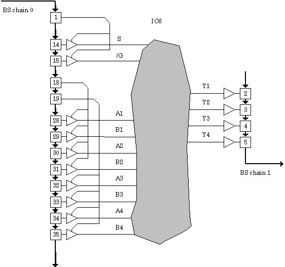
The second cluster comprises only a single IC (the
74LS157) and is surrounded by BS cells of both chains, as shown in figure
2.

Figure 2: The 74LS157 single-IC non-BS cluster.
The information required for generating the test program
segment concerning this cluster, besides the test vectors generated
externally, comprises the elements presented in table 3.
| Parameter | Value |
| Number of BS chains surrounding the cluster | 2 (chains 0 and 1) |
| Information concerning BS chain 0 | |
| Number of BS cells | 13 |
| Identification of the BS cells | 1,14,15,18,19,28,29,30,31,32,33,34,35 |
| Information concerning BS chain 1 | |
| Number of BS cells | 4 |
| Identification of the BS cells | 2,3,4,5 |
| # of cluster inputs that are also primary inputs | 0 |
| # of cluster outputs that are also primary outputs | 0 |
| Guard values required? | No |
Again there are no primary input or output pins that are also inputs or outputs of the cluster, and it is not required to apply guard values to the cluster inputs during the remaining steps of the test protocol.
The GenRad HILO test vector generator produced for this
second cluster again 5 test vectors, providing 100% fault coverage of
stuck-at pins in the 74LS157. In this case, however, the test vectors will
be applied through the BS cells of chain 0 and the test responses will be
captured through the BS cells of chain 1. These 5 test vectors, their
expected responses and masks, for both chains, are shown in table 4,
already inserted into the proper places in the stream of cells that
surround the cluster (the same rules apply as in the previous case, now
with cells 1 and 2 in the leftmost locations for the two BS chains).
|
# vectors |
BS chain |
To shift in |
Expected values |
Mask data |
|
5 |
0 |
0000011111010 |
1111111111111 |
0000000000000 |
|
1 |
1111 |
1111 |
1111 |
Notice now that all values in the "shift in" column for chain 0 carry meaningful data, since all these 13 cells play a role in applying each test vector to the cluster inputs. However, for BS chain 0, there are no expected values known and therefore all mask data bit streams contain only 0s. As for BS chain 1, the shift in data is meaningless (since these cells are only used for response capturing), but all bits have known expected values for each vector.