[previous] [next]
[contents]
![]() Boundary-scan
test - The TAP controller
Boundary-scan
test - The TAP controller
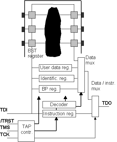
The block called TAP controller in figure 1 is a small finite state machine (FSM) that generates the control signals defining the operating mode of the existing registers and of the data / instruction multiplexer (the 2:1 multiplexer that selects between the instruction register or a data register).

Figure 1: The BS architecture at IC level.
The TAP controller FSM is controlled by the TAP pin called TMS and enables three main operations on the register placed between TDI and TDO:
- To capture the logic value present at the parallel input of its cells.
- To shift data serially through the register cells.
- To update the cell parallel outputs with the values that were shifted in.
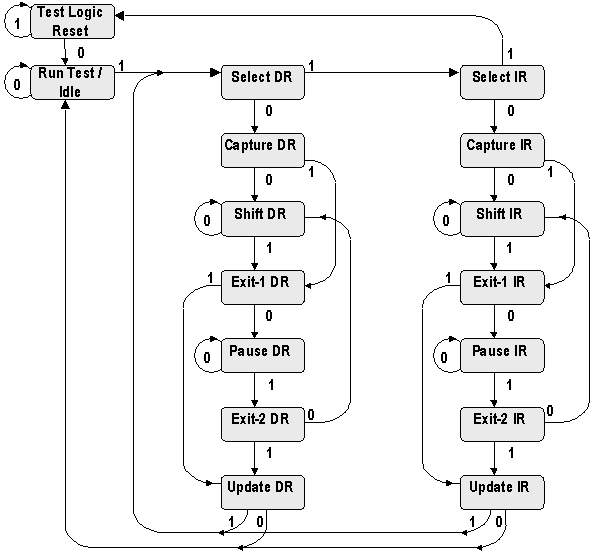
Each of these three operations may take place on a data register or on the instruction register, leading to two parallel and similar paths in the TAP controller state transition diagram, shown in figure 2:

Figure 2: The TAP controller state transition diagram.
The IR (instruction register) branch is the right one and the DR (data register) branch is at its left. The three operations previously referred correspond respectively to the Capture, Shift and Update states (-DR and -IR). The Test Logic Reset (TLR) and the Run Test / Idle (RTI) are also important states, with the following objectives:
- The TAP controller is forced into the TLR following power-up. In this state the BS logic has no effect at functional level, since all BS cells are in transparent mode.
- RTI is a state where certain test operations defined by optional instructions (such as BIST) will take place.
The Select, Exit1 and Exit2 states (-DR and –IR) are temporary states. The last two, combined with the Pause (-DR and –IR) state, allow shifting of test data to be temporarily halted. The Select (-DR and –IR) states allow the selection of the type of register (-DR and –IR) to be connected between TDI and TDO (since there is only one TMS input, an additional state is required to distinguish if a DR or IR operation is to follow after RTI). It is important to understand the timing of the actions associated with the TAP controller FSM, namely that:
- State transitions occur with the rising edge in the TCK signal.
- Actions in a TAP controller state (such as capture, shift or update operations) occur with the falling edge of TCK in the state.
These requirements aim at guaranteeing correct operation even with BS chains including thousands of cells. Notice in particular that TDO changes at the falling edge of TCK, while TDI is read at its rising edge (both operations occur during any shift operation in the BS cells).