Fig. 1: A small application example.
The required test code segment should enable the following controllability / observability operations:
- Control of the array of leds through the BS register present in the 74BCT8244 TI SCOPE octal
- Observation of the logic values captured at the eight input pins
The corresponding sequence of test actions comprises the following steps:
- Place the BS infrastructure in EXTEST mode, so that each led is driven from the BS cell associated with the corresponding output pin
- Shift in the bit sequence (test vector) that produces the required pattern in the array of leds
- Check that the bit sequence shifted out (not really test responses, since no previous test vector had been applied) shows that each input pin is connected to +5 V
The test code segment shown in figure 2 may be used to carry out this experiment, assuming that the circuit is connected to TAP0 (the arrow shown on the left indicates the last instruction executed). This test code segment may be downloaded as a JTAGer file (jtager1.bst), in case the reader wishes to carry out this experiment.
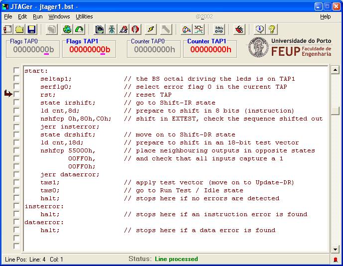
Fig. 2: Main JTAGer window and test program source for this example.
Following the execution of the test program sequence shown above, the array of leds should display an ON/OFF/ON/... pattern. The reader is invited to experiment with the various tools and utilities available (e.g. State Diagram, Waveforms, etc.), and in particular to use the Bitstream shifter utility to reach the same results, in order to enable a comparison of test program execution and interactive interface methods.