
The Project
Before delving into what I'm currently working on and the decisions made until now, I think it’s best to explain the main goal and objectives of this work. The main goal of this project is the design of a current reference that has an overall precision of +/-5% over PVT.
| Goal | Conditions |
|---|---|
| Overall Precision <+/-5% | Supply Voltage: 1.62 V to 3.63V |
| Temperature Range:-40°C to 125°C | |
| All Corners and MonteCarlo |
What the table means to explain is that my objective is designing a reference that will never go above 5% variation over the voltage supply considered, temperature range and eventual manufacturing deviations.
Voltage Reference Topology Used
In order to reach such goal it was done extensive research in state of art solutions for this problem. One of the difficulties I found during my research was the lack of concrete data. Nearly all of the articles only provided results under certain conditions, like a certain variation over temperature but at a fixed voltage. Other articles claimed their topology was PVT invariant but provided no results of process compensation or variation.
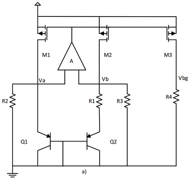
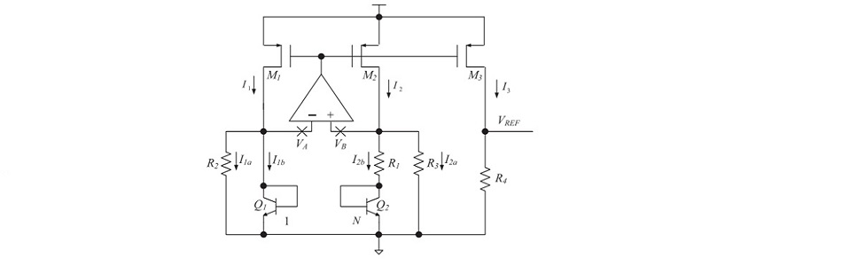
The picture above shows the basic topology chosen for this work. A copy of the article I based on can be found here.
This topology works by adding two voltages that have opposed scaling in regards to temperature. We add a CTAT voltage that decreases with temperature, to a PTAT voltage that grows with temperature. With proper weighing, the temperature variation is virtually eliminated. And since the weight of each portion is based on the ratio between resistors R4/R1 for PTAT and R4/R3 for CTAT, the process dependency is also slightly smaller.
The PTAT current is generated by applying a differential base-emitter voltage from the NPN bipolar transistors over R1. The AMPOP ensures a virtual short at VA and VB, so VB is in fact the base emitter voltage from Q1.
Since VB is the base emitter voltage from Q1, the CTAT current is generated across R3. These two currents are then summed and applied over R4 due the current mirrors by M1-3.
Voltage-Current Converter
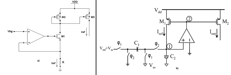
The last step in our circuit is adding a small voltage-current converter with small variation. This topology uses an AMPOP in a slightly different voltage follower configuration. Examples of similar topologies can be found here and here.
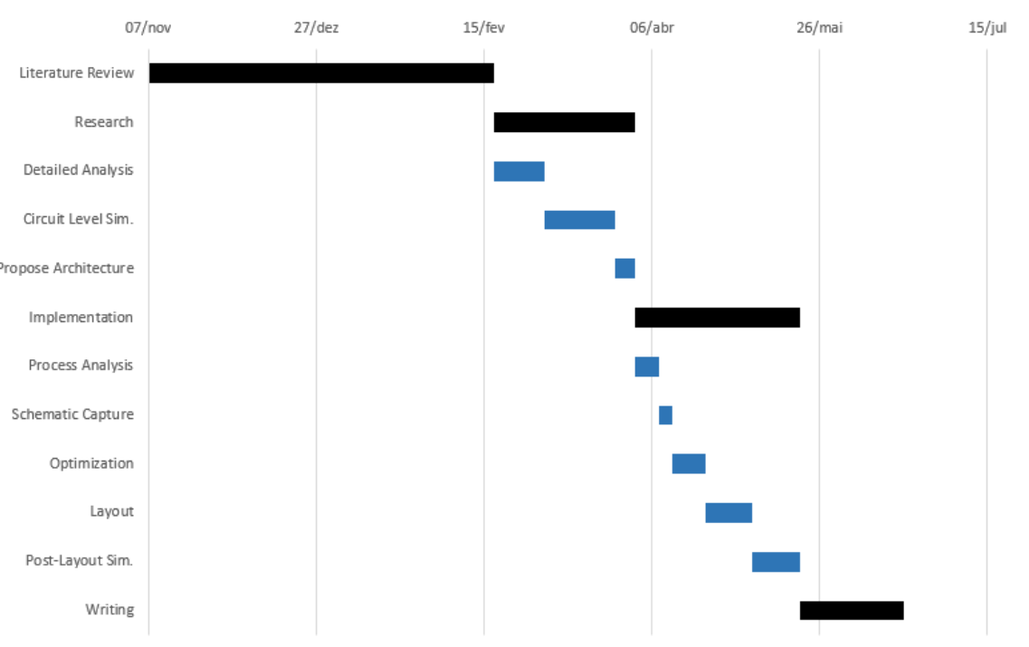
Work Plan
A Gantt Diagram is shown below with my work plan. Bigger deadlines are highlighted in black while smaller steps are in blue. The two Major deadlines correspond to the "detailed circuit simulation and characterization" and the next one is "layout design and full post-layout validation".