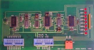
Figure 1: A simple demonstration board used for hands-on sessions.
The board will be described in first place, followed by the analysis of the information required for test vector generation and, in the last section, by the test program generated for all steps in the test protocol, assuming the BS test controller model presented in the previous chapter.
The demonstration board used in this chapter was previously developed as part of an ESPRIT project (EP2478, Research into Boundary Scan Test Implementation), at the time with the objective of validating a set of test vector generation methodologies. The main characteristics of this board are the following:
- There are two BS chains: The first chain (BS chain 0) includes the BS components IC3 and IC4 (both of them the SN74BCT8244) and the second chain (BS chain 1) includes the BS component IC5 (again the SN74BCT8244).
- There are two non-BS clusters: The first cluster comprises the non-BS components IC1 and IC2 (respectively the 74LS139 dual 2:4 decoder and the 74LS04 hex inverter) and is completely surrounded by BS chain 0. The second is a single-IC cluster that comprises the non-BS component IC6 (74LS157 quad 2:1 mux) and is surrounded by BS cells of both chains.
- A total of 17 jumpers enable the insertion of open or short-circuit faults for test program validation purposes.
- There are 8 primary inputs (I[0..7]) and 8 primary outputs (O[0..7]).
The complete schematic diagram (PDF with 204 KB) of this board is available to enable a detailed analysis of the circuit and its BS infrastructure. However, and to make it easier to understand this case study from the testing point of view, an alternative representation emphasising the two BS chains and the two non-BS clusters is shown in figure 2.
Figure 2: BS chains and non-BS clusters in the demonstration board.
The SN74BCT8244 data sheet (also available from TI’s web site at www.ti.com) includes all the information concerning the BS architecture present in this component, which in fact includes several optional instructions specific of TI. However, and since the basic steps of the test protocol presented in an earlier chapter did not make use of optional instructions (which were only referred as a vehicle for optional steps in this protocol), the complete test program will only be based on the three mandatory instructions described in the IEEE 1149.1 std.